Getting started with wiring is the most difficult part for this swap. Because there are wires everywhere, there's no clear starting point, but don't let that discourage you. Just pick something and go for it; everything else will fill in from that point.
The following is the result of all the information I have gathered from other sources, be it my Bentley wiring diagrams, information from Volkswagen, or information aquired elsewhere. In particular, Andyd's checklist has been helpful in moving through this. I'll reproduce it below with my own notes and modifications for the U.S. spec '96 Passat wiring harness.
Contents
- Under-dash Plug Location Checklist
- ALH Injection Pump Swap
- Additionally: Cluster Pinout and Differences
- Additionally: Fuse Box Pinout
Under-dash Plug Location Checklist
Notes: The plug descriptions denote the names and/or functions of the circuits involved. The letter codes denote the plugs in the back of the fusebox. There is a small unlocking bar in the middle that must be slid out before individual plugs can be disconnected or reconnected.
Also, it should be noted that I am starting from a complete, unmodified wiring harness from a 1996 Passat TDI sedan. I suspect that some of the European Golfs and similar may have had a significant portion of the headlight loom taped to the engine wiring harness. For the U.S. spec Passat this is not the case.
| Plug description | Pin Count | Plug Colour | Wiring Colour | Destination in the Van | Completed? |
|---|---|---|---|---|---|
| G1 | 12 | White | Various | G1 in fusebox | √ |
| G2 | 12 | White | Various | G2 in fusebox | √ |
| F | 10 | White | Various | F in fusebox | √ |
| Cruise control plug | 4 | Black | Black, Blue, Red, White/Black | Harness obtained from Passat replaces harness in van. See below for details. | √ |
| J362 K-Line | 1 | Brown | Grey/White | K-Line (TODO) | √ |
| Z1 Glow plug supply | 1 | Yellow | Red/White (Thick) | Z1 in Fusebox | √ |
| F36Clutch Pedal Switch (Taped to Pot) | 2 | Black | White/Red & Brown/Blue | Clutch pos sensor | √ |
| F47Brake position sensor(Taped to Pot) | 2 | Blue | White/Yellow & Brown/Blue | Brake pos sensor | √ |
| T6Accelerator potentiometer | 6 | Black | Various | Pedal Potentiometer (wherever you installed it) | √ |
| VSS | 1 | Blue | Blue/White | TV13 Speed Signal Junction Box (Blue junction box connector on top of fusebox). From here it goes to U1/1 on to T28/27 (See this TDIClub Post) | √ |
| T3b Injection Signal | 1 | Black | Violet/White | MFA Only. From T68/9 to T3b to T28/26. Comes with Passat cluster harness or add to van | √ |
| T68/44 Brake Pedal Signal | 1 | Green | Black/Red | W connector removed from Passat Fusebox. This allows connection of this plug to W/4. Signal from M9 and F/2 | √ |
| Starter Lockout | 2 | Black | Black/Red & Red/Black | Starter - Needs to run from solenoid to F/1. The two pins on this plug must be jumped with a clip obtained from the Passat harness. | √ |
| Cruise control Between E45 and TV5 | 1 | Green | Black | Possibly Green junction box connector above fusebox (Eventually to Terminal 15 12v supply). See below for details | √ |
| T2d | 2 | Black | Brown/Yellow, White/Red | Outside Air Temp- MFA Only, connects G1/2 and G2/2 to sensor. The connector is labeled "in the engine compartment" on diagrams. |
Unused |
| ? | 1 | Grey | Brown/Blue | (TODO) T68/28 - J246 Magnetic Coupling Cut-out relay for Air Conditioning | |
| to F38 | 1 | Yellow | Green | (TODO) T68/37 - F38 Ambient temperature switch. Used to disable A/C only when RPM drops below idle. Will verify this when running. | May look into |
MFA and General Cluster Notes
There are a few functions wired in for the MFA gauge clusters that were never offered with the B4 Passat TDI. You can, however, get a cluster from a 95-97 VR6 and a few plugs and sensors to adapt it to the wiring harness. To be honest I'm not sure the additional instrumentation is worth it beyond oil temperature, but I did build an outside (and inside) air temperature reading into my thermostat, which is a project that will be posted here later.
At any rate, the MFA-only plugs are not needed for the engine to operate properly and can be left unplugged.
Whether you want the MFA cluster or not, I recommend taking the white T28 harness from the Passat. This has a few differences, but most importantly Pin 27 for the speedometer is not populated on the van harness. Additionally, all the MFA sensor wires and the Violet/White injection signal wire are present, although the mystery T28/28 wire is now red/white. This wire is not shown in any diagram I can find. On my van it was spliced into fused +12v, and on my Passat I traced it physically back to the Pin 7 (K line) on the OBD connector. Apparently these clusters can speak KWP?
 When using the B4 Passat harness, one important change is made on pin 13 of T28: in the bus it connects to U1/4 and gets power from fuse 16; the Passat harness connects T28/13 to U2/1, which is connected through a four-place jumper block from E/2 to D/8, getting power from, apparently, fuse 16. In the Passat, find the two wires from E/2 to D/8 and de-pin them, moving them to their place in the bus. I snapped the jumper block TV4 onto TV13 that I added earlier. After that you will have power to your cluster on pin 13 when the ignition is on. Progress!
Cruise Control, VSS, and pedal switches
The TDI uses drive by wire with no pedal feedback. As a result, the cruise control module 443907305A (under the dash) can be disconnected. In the engine bay, the vacuum pump can be disconnected and removed and the wiring pulled out of the firewall. This will leave the W connector on the fuse box, which can also be disconnected. Mine had a blue/black wire spliced into the connection from D/9, which is fused B+. I don't know if this is standard, but it seems like it isn't.
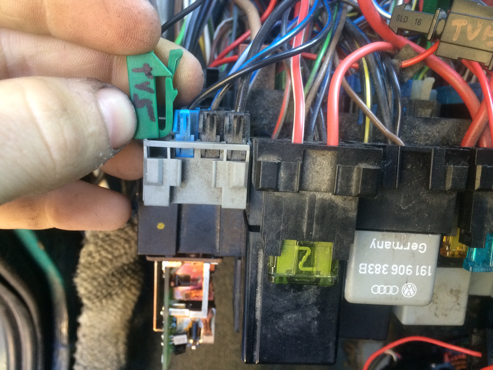
The speed signal comes in from the ECU at T68/43 on a blue/white wire and connects to TV13. This is TV13:

 Remove the W connector from the Passat harness. It has two wires— a Blue/White and Black/Red. The Blue/White at W/1 also connects to TV13, which is snapped into the fusebox where you removed it from the Passat box— just adjacent to the W connector.
The other connector, W/4 Black/Red connects to T68/44 through TV11, which is the very connection you make when you plug the wire from T68 to the wire from the W plug. You can check another plug off your list.
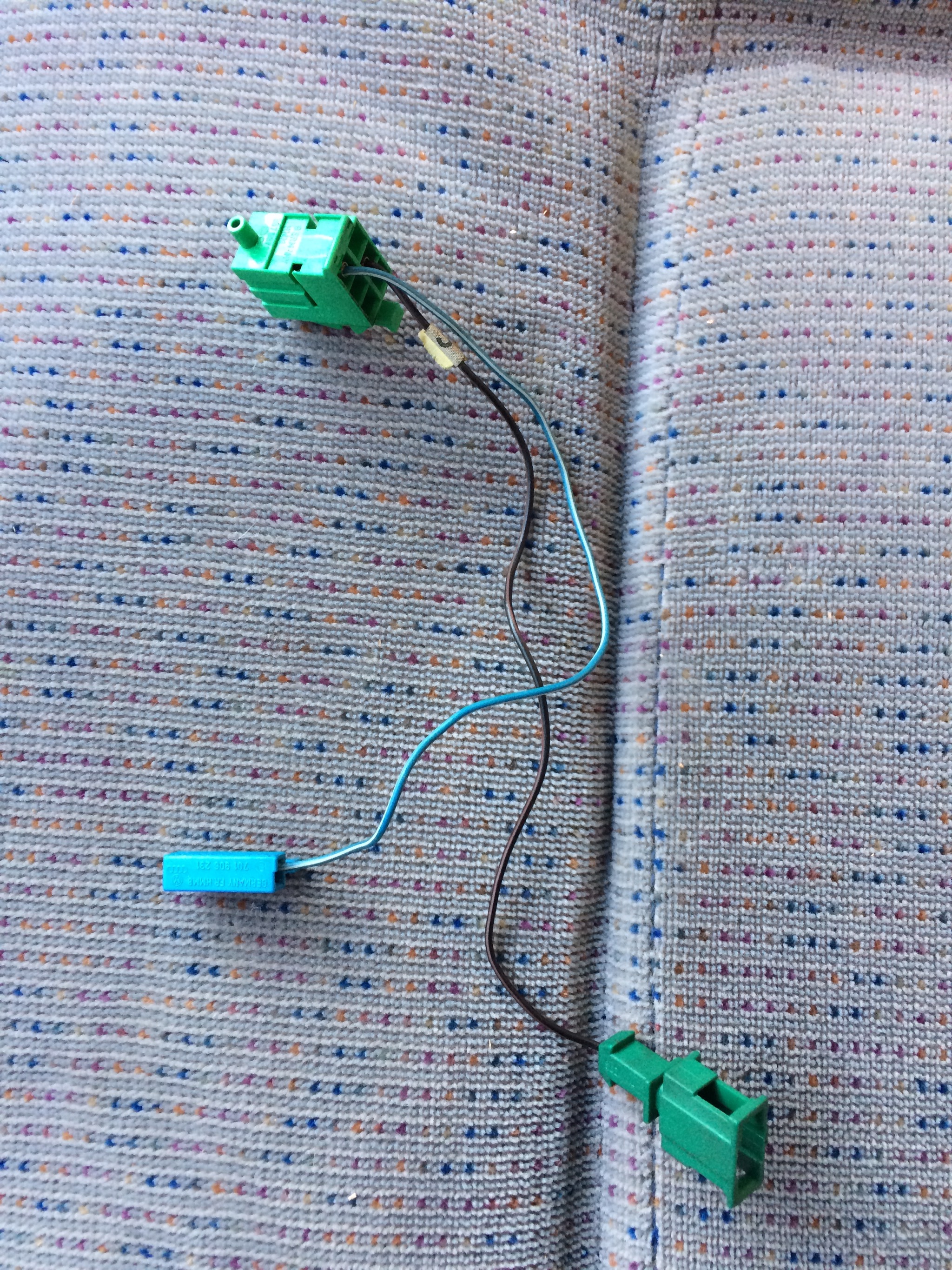
You will also need to connect the stalk to the ECU, which now controls cruise rather than the box under the dash. The harness you removed earlier plugged into a 4-pin connector (henceforth called the 2x2 connector due to its layout). Look for Black/White, Red, Blue, and Black wire. This threads up to the stalk connector in the steering column. Replace it with the one from the Passat, where both ends are 4x1. The Passat harness has the same wiring colours and plugs into the harness headed for T68 except for one wire.
 The black wire coming from the 4x1 connector terminates in a green single plug that needs to connect to TV5. TV5 is another four-place jumper block on the fuse box deriving its power from D/11. Luckily it's present on the Eurovan on the left side and one place is open. Cruise now has power.
If you're running a VNT turbo using an AFN tune, see VNT Considerations, below for additional information about T68/58.
Brake and Clutch switches
The TDI ECU needs three connections for these two pedals. Without them you will have no cruise or worse— a flashing glow plug light and a code. These are a little confusing to think about because you have to reorient your brain to the idea of "unpushing" a button— when you push the pedal, the switch returns to its normal position.
- Brake Pedal F: used to send power to the brake lamps (and the ECU takes note of this). This is taken care of above when the green plug from T68/44 is plugged in. Normally closed, but held open by pedal when it's up.
- Brake Pedal F47: ECU holds the signal on T68/20 high when disconnected, and the switch pulls it to ground. Normally open, but held closed (low) by the pedal when it's up.
- Clutch Switch F36: ECU holds the signal on T68/17 high when disconnected; the switch pulls it to ground. Normally open, but held closed (low) by the pedal when it's up.
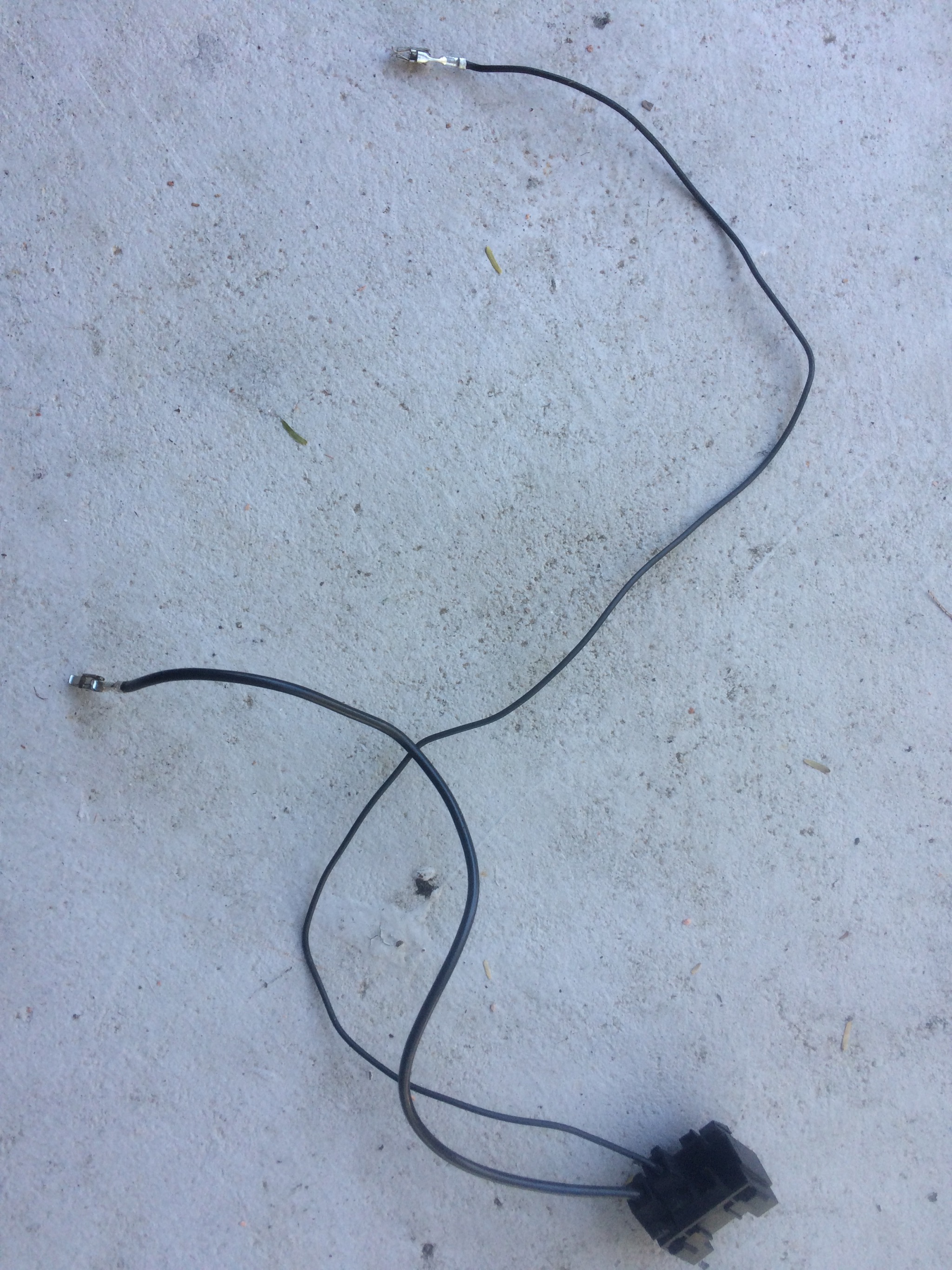
Neither F47 or F36 switches fit in the Eurovan brackets without modification. I suspect that the clips could be broken and the Passat plugs would fit on the Eurovan switches, but I was unwilling to experiment with it. This was an area where I finally cut and soldered something on the harness beyond just lengthening the MAF sensor wires. Get the Eurovan's old cruise control harness and cut the Red/Black wires to separate the two black plugs (and also cut them apart from one another; the circuit works differently). Cut off the Passat's brake and clutch plugs for F47 and F36, respectively. Prepare some heat shrink and then solder the Eurovan's black plugs in place of the Passat's plugs. If you're running a VNT turbo, though, see VNT Considerations, below.
OBD Connector
The OBD connector is comprised of three signals— 12 volt power, ground, and the K line. The K line implements a data bus using KWP-1281, which means that one wire (in this case) carries the communications for all controllers. In the A3 and B4 the only controllers were the ECU on channel 1 and the airbags on channel 15. Since the Eurovan doesn't have airbags (and thus no controller), you can handle this a a few different ways.
The K signal comes from the Grey/White wire to the single Brown connection. In the B4, it then is crimped from the factory to three more connections, one of which is the OBD connector. I chose to salvage all of this, so the connections are as follows:
- T1y from the ECU
- T28/28 from the cluster
- A white terminal block connected to the fuse block
- J362 OBD port
The white terminal block is where the airbag controller would be plugged in. I kept it because I wanted to keep things clean and there's a non-zero chance that I'll want to implement my own KWP1281 controller in the future (to complement the OBD software I've written for the Mac).
This is also where I snipped the first wires out of the Passat harness; to this point everything has been unplugged and de-pinned. The power from the port is scavenged from the radio 12v line, so I cut the radio out of the Passat harness. Similarly, the ground is shared and a few wires there need to be snipped out to remove the OBD port from the Passat. Be careful not to snip either of the two ground wires going to the OBD port— officially it needs both chassis and signal grounds (although VW chose to simply jumper them).
I had a dangling single fuse block on the van that gets power from Y/2, which is described as "Starter interlock / Power window power". I don't have a starter interlock, and my power windows work fine without it plugged in, so I inserted the pin from the OBD port into this side of the fuse. This way the OBD port is fused alone, which is great for the dodgy cables I sometimes test. This does mean, however, that the OBD port is live even when the key is off. The ECU won't be there to listen, but some dodgy cables might not reset properly. Time will tell if I need to splice something finally.
The ground comes from the same place as the Passat— E/5 is open on the van and is the specified place for the diagnostic connector ground. With this, it's time to fire up a scan tool (one that doesn't cost hundreds as it's just not worth it for these cars).
Emissions (and Emitting) Equipment
There are three pieces of emissions equipment that need to be dealt with in order to satisfy the computer. Only one, the N18 valve, is arguably useful
- G20 and G132 Catalytic Temperature Sensors (1 and 2, respectively)
- V54 Smoke Metering Pump
- N18 EGR Solenoid
The catalyst heating system was deemed a bad idea and deleted with a ECU replacement, and good thing: the replacement GQ ECU is far easier to modify for, say, running a VNT-based turbo. The catalyst heating system worked by literally spraying raw diesel into the exhaust ahead of the cat. Similar systems work well for RC aircraft as a smoke trail system; the results in the B4 cars was the same (ok, to a lesser degree). Since it's a deleted system, retrofitting the bus would make no sense. However, codes will be generated, check engine lights lit, and emissions tests automatically failed without these dealt with.
The catalytic temperature sensors can be simulated by 270 ohm resistors. Simply push them into the plug to confirm (I have seen some internal resistance differences between ECUs that I haven't bothered researching) and then solder into place and cover with heat shrink. The absence of these sensors will trigger
The V54 Metering Pump will never be activated, but its presence is checked for, so it can be simulated by a 10 ohm resistor. It's probably prudent to use a 10 watt resistor as the theoretical power dissipation could be in the order of 14.4 watts, but I image the check is probably very, very brief. It doesn't need to sustain that kind of power for continuous use. With a BK computer the absence of this pump will trigger code 01242 "Final Stage in Control Unit". On the GQ ECU it will trigger 00309 "Washer Solution Metering Pump V135". Oh, for the love of documentation.
The N18 EGR valve can be used if desired (and if there is hardware for it to actuate), or can be simulated by a 30-40 ohm resistor. The same situation of power- dissipation applies from above. If you can find a 10 watt, go for it and never worry again.
VNT Considerations
This section is a work-in-progress as of Jan 2016.
Software from a '97 B5 Passat with an AFN engine can be adapted to run a VNT turbo. If you're not interested in anything other than burning eeproms, I believe the AFN used a VNT1749VA (commonly called a VNT-15). The ECU of interest used part number 028906021GL.
This software doesn't throw check engine lights relating to the smoke injector or catalytic temperature sensors. It may expect a "J232 Fan Relay," but I haven't yet gotten a code for not having one. One thing that is notably different is the brake and clutch switches (F47 and F36, respectively). They expect to be connected to fused +12v rather than ground.
F47
Unfortunately, the ECU has an internal pull-up resistor for F47 which I was unwilling to find and desolder. The switches just don't close at the same time and I was unable to adjust the old vacuum switch position. Instead, I defeated the careful German design (seriously, read the Funktionsbeschreibung on this system alone) by making a simple transistor circuit, shown below.
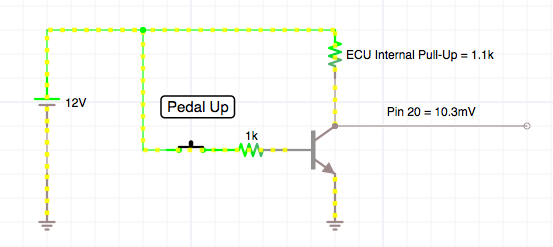
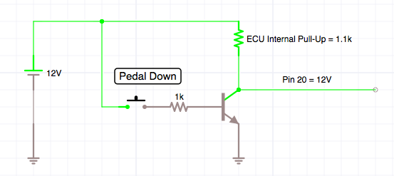
![]()
F36
For the F36, the ECU needs to see +12v when the clutch is depressed. The line on T68/17 floats when the clutch is up, and is probably pulled low by the ECU. Unfortunately, the switch included in the Eurovan is normally connected when the pedal is up and disconnected when the pedal is depressed.
The easiest way to handle this is probably to leave both terminals of the switch connected to T68/17 and ground, and then add a 800Ω or so pull-up resistor from T68/17 to +12V. This way, when the pedal is up, the switch will connect T68/17 to ground. When the pedal is depressed the switch will disconnect and the resistor will feed voltage to T68/17 as designed. I cut a plug terminal off the B4 harness to plug into a black connection for switched power on the fusebox. The only splicing is done next to the pedal itself.
Cruise Control (FGR)
There is a slight difference in the harness for the B5 AFN (with same T68 harness) and the B4 harness. The AFN programming (I'm using 028906021GL) expects to see +12v on T68/58, but this pin is not connected on the North American B4s. The pin can be removed from the small two-pin harness inside the B4 driver's door-- I think it's for the red LED. It will be obvious as its pins are the smallest in there.
After hard-wiring this to switched +12v the cruise control works, although I get a code if I turn the switch off. The proper way to fix this would be to splice this pin into T68/66 which is hot only when the cruise switch is on.
ALH Pump Conversion
If you have machined a bracket in anticipation of running an ALH pump, there is an additional variable to throw in the works. Luckily the 1Z computer will run an ALH pump just fine (at least electrically— there may be some tuning to consider). Volkswagen simply changed from using two plugs to one 10-pin plug, part number 1J0973735. These were also used (probably more commonly) as headlight connectors. eBay seems to be a fine source.
A word of caution: in some cases the injection pump harness wires with very similar colors but carrying different signals. In any case, these can be traced back to their origins at the T68 connector.
You have a choice of how to wire the T3 connector. Because the original path routes through the T24 Multiplug (Orb of Death), if it's transfered to the new 10-pin ALH plug the wiring harness that stays with the engine will be joined to the harness that is wired to the ECU and fusebox. This would make future removal of the engine far more involved and would require final wiring assembly to be completed after the engine was installed. This may be perfectly acceptable to you (and carries the benefit of not modifying the engine-side harness), but because of these issues I chose to de-pin the three wires from the T3 connector and re-insert them into the new ALH 10-pin connector. One wire (the white and black one) has a smaller end connector and will need to be cut and spliced to a larger connector. These came with my 10-pin plug but can also be sourced through the dealer.
| 1Z/AHU Pin no | 1Z/AHU Wire | ALH Pin No | ALH Wire |
|---|---|---|---|
| T8/1 | lilac/black | T10/1 | lilac/black |
| T8/2 | grey/green | T10/2 | grey/green |
| T8/3 | white/green | T10/3 | white/green |
| T8/4 | brown/blue | T10/4 | brown/blue |
| T8/5 | black/yellow | T10/5 | red/lilac |
| T8/6 | brown/yellow | T10/6 | brown/red |
| T8/7 | yellow/black | T10/7 | yellow/red |
| T3/1 | white/black | T10/8 | black/white |
| T3/2 | brown/black | T10/9 | brown/black |
| T3/3 | black/yellow | T10/10 | yellow/black |
![]()